Exclusive IPD distributorfor the Czech and Slovak RepublicsOriginal components · CAD/CAM libraries · technical support+420 604 483 343obchod@exklusiv-dent.cz
Clinical-laboratory MUA protocol

Multi-Unit from fixture to CAD:placement, scanning, Exocad and passive-fit verification.

Explore the MUA → scan → CAD workflowIPD Solutions Map · clinic ↔ laboratory

A practical workflow from a correctly seated straight or angulated Multi-Unit abutment through an MUA-level digital reference to direct-to-MUA design, a verification prototype and the definitive screw-retained restoration.

Unigrip / HEX 2.0AB‑SR‑00 / 01AB‑SR‑11 Scan TransferTECH / LITEExocadverification jig
Step 1 · establish the mechanical reference first

Before scanning, the Multi-Unit must be correctly seated and tightened

A scan body transfers into CAD the position of the prosthetic platform physically beneath it. The digital workflow therefore starts before the scan, with correct MUA selection, complete seating, the appropriate instrument and the torque specified for the exact reference.

1Implantverify the system and platform
2MUA0° / angulated, GH, REF
3Tighteningcorrect instrument + torque
4MUA scanengaging / non-engaging / transfer
5LibraryTECH or LITE
6CADdirect-to-MUA / interface
7Verificationphysical prototype before definitive fabrication
IPD Unigrip driver
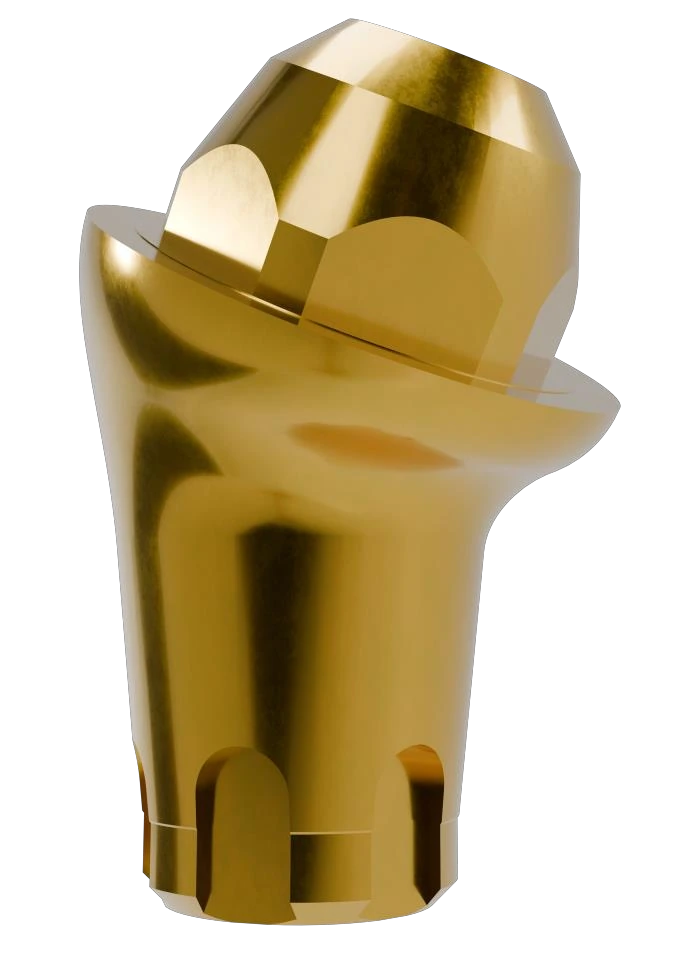
Angulated MUA

Primary screw → Unigrip

For angulated MUA with a primary Unigrip screw, select the instrument length according to access and working depth. The IPD catalogue lists overall lengths of 18, 25 and 32 mm.

PU‑00‑18PU‑00‑25PU‑00‑32

Practical guide to usable reach:approximately 8 / 14 / 23 mm.*

Unigrip in the e-shop
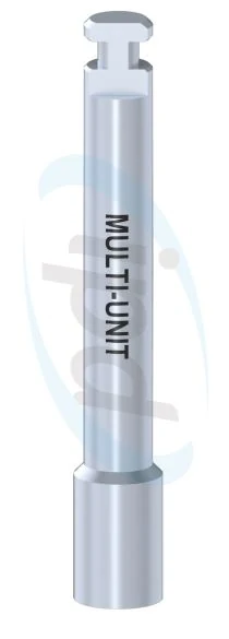
IPD LL-AB-00 HEX 2.0 driver for straight Multi-Unit
Straight MUA

External hex at the top → HEX 2.0

A straight Multi-Unit is inserted via the external hex on its coronal portion. The system instrumentIPD/LL‑AB‑00has a HEX 2.0 working profile and an overall length of 20 mm.

IPD/LL‑AB‑00HEX 2.020 mm
LL-AB-00 in the e-shop
C1030 adapter for RA shank and torque ratchet
Connection to the torque ratchet

C1030 · ratchet eye approximately Ø7 mm

The adapter connects RA-shank instruments to a ratchet with the corresponding eye. In practice, Ø7 mm covers a large proportion of commonly used instruments, but ratchet-eye diameter is not a universal standard.

C1030 in the e-shop
RA adapter for a different ratchet-eye diameter
Instrumentation exception

C1031 · ratchet eye approximately Ø8 mm

If the torque ratchet has a larger eye, use the corresponding Ø8 mm adapter. Before clinical use, always verify full insertion of the RA shank and secure engagement of the adapter physically.

C1031 in the e-shop
* The usable-reach values of 8 / 14 / 23 mm are practical guidance dimensions used by Exklusiv Dent; the official IPD catalogue confirms overall lengths of 18 / 25 / 32 mm. For manufacturing or metrological specifications, verify the current instrument drawing.
Step 2 · torque is not a property of the term “MUA”

Tightening torque belongs to the exact reference, not to a general category

IPD publishes different torque values according to implant system, platform and exact Multi-Unit reference. It is therefore not safe to assign one universal value to all straight MUA or one universal value to all angulated MUA.

Straight MUAREF-specificCurrent IPD product data include, for example, straight MUA specified at 35 Ncm. Verify the exact value for the specific REF.
Angulated MUAREF-specificCurrent product ranges include, for example, published values of 20 Ncm; an older generic IFU also stated 15 Ncm. The current exact REF governs.
AB‑SR‑00 / AB‑SR‑0115 NcmCurrent IPD data for the RP Ø4.8 scan body, HEX 1.2. These are specific AB references, not a universal scan-body torque.
AB‑TR‑0015 NcmCurrent IPD data for the standard RP Ø4.8 MUA prosthetic screw with a Unigrip head.
Safety rule:never transfer a torque value from the table to another series simply because the component looks similar. Before tightening, verify the implant system, platform, exact REF and current IPD product data / IFU.Open the tightening-torque page →
Step 3 · scan the prosthetic level on which you intend to design

Engaging, non-engaging and Scan Transfer are not three names for the same thing

Once the MUA has been definitively seated, its position is transferred into CAD at theMulti-Unit level. This is fundamental: an implant-level scan body cannot simply be “switched” to MUA later in CAD because the actual position of the abutment would never have been measured.

IPD/AB-SR-00 · engaging

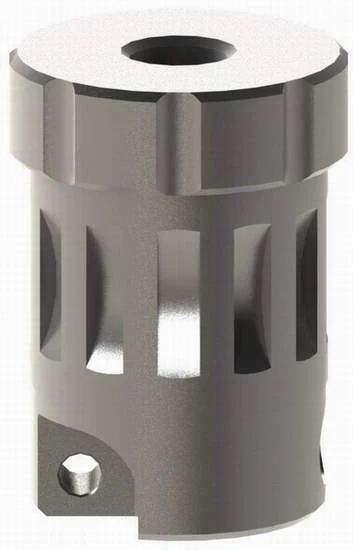
An anti-rotational scan body for RP Ø4.8. It is appropriate where rotational orientation must be transferred and the specific MUA / library supports this indexed workflow.

  • engaging geometry
  • HEX 1.2 · 15 Ncm
  • particularly useful for single-unit restorations where the specific MUA is indicated for a single-unit workflow
Find AB‑SR‑00

IPD/AB-SR-01 · non-engaging

A rotational, non-engaging scan body for RP Ø4.8. This is a typical pathway for splinted restorations on multiple MUA where an anti-rotational index at each individual interface is not desired.

  • non-engaging geometry
  • intraoral and model / extraoral scanning
  • HEX 1.2 · 15 Ncm
Find AB-SR-01
IPD Scan Transfer at Multi-Unit level
Alternative for full-arch

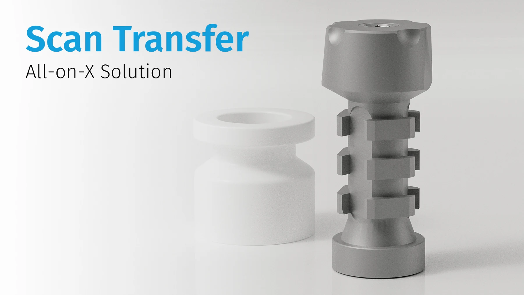
IPD/AB‑SR‑11 · Scan Transfer

In a full-arch case, the way the scanner transfers relationships between distant MUA positions may be more important than the local scan body alone. Scan Transfer creates an additional physical reference pathway for full-arch protocols and uses its own corresponding library branch.

MUA indexing:IPD lists its current straight Multi-Units for both single and multiple restorations. This does not mean that every MUA in every compatibility family can be treated interchangeably as engaging or non-engaging. Always keep the exact MUA, scan body and library within one verified workflow branch.
Step 4 · the geometric bridge

TECH or LITE? The decisive factor is the scan body that actually measured the MUA level

Both branches can lead to an IPD prosthetic solution, but they do not start from the same scanning geometry.

IPD TECH MULTI UNIT

IPD scan body
  • the input corresponds to IPD scan-body geometry, for example AB-SR-00 / AB-SR-01
  • CAD matching must use the exact MUA platform and the correct engaging/non-engaging branch
  • available direct-to-MUA, interface or provisional options then follow according to the specific library

IPD LITE MULTI UNIT

OEM / third-party
  • the input is a supported OEM or third-party MUA scan body
  • after correct matching, LITE allows the workflow to continue to the corresponding IPD components
  • this does not correct an implant-level scan: the input must still represent the actual MUA level
Step 5 · Exocad

From MUA scan body to direct-to-MUA design: verify the geometry at every transition

Option names may differ between Exocad and library versions, but the geometric logic remains the same. The key requirement is that every step represents the same physical MUA platform.

Import the clinical or model data and verify case orientation

Load the STL/PLY data according to the scanner used, together with the opposing arch and bite. Before matching, verify that the MUA scan bodies were fully seated and are clearly captured in the data.

Select the exact MUA library and the correct scan body

Use TECH for IPD scan-body geometry and LITE only for a supported OEM/third-party MUA scan body. Distinguish engaging from non-engaging. In a full-arch case, the wrong library can produce a very precise wrong result.

Perform matching and visually verify every individual MUA

Do not rely on automatic best-fit alone. Check the seating of the library geometry on each scan body, its orientation and consistency across all positions. If one position does not match, do not solve it by globally “averaging” the entire restoration.

Select the restoration branch

Depending on the library, the workflow may use a direct MUA interface, a direct-to-MUA PMMA/provisional branch, a Ti-base / interface or a supported ASC option. The choice must match the definitive material and the fixation screw being used.

Design the screw channels, restoration volume, occlusion and hygienic profile

In a full-arch restoration, assess not only aesthetics but also instrument access to each screw, sufficient material around the channels, connector cross-sections, gingival clearance and access for clinical hygiene.

Before export, isolate each interface and perform a final check

Inspect the restoration from the basal side and verify every MUA interface, rotational logic, screw-channel axis and any ASC support. Only then export the manufacturing file.

Direct-to-MUA does not mean “any scan → any MUA library”.IPD explicitly states that designing on the Multi-Unit level requires acquisition with an MUA scan body or Scan Transfer, followed by use of the corresponding MUA library.
Step 6 · before committing to expensive definitive material

Not a “mock-up”, but a verification prototype and passive-fit check

A mock-up usually describes an aesthetic or functional simulation. If the aim is to verify whether a digitally designed MUA restoration physically seats without obvious internal strain, “verification prototype” or “verification framework” is more precise.

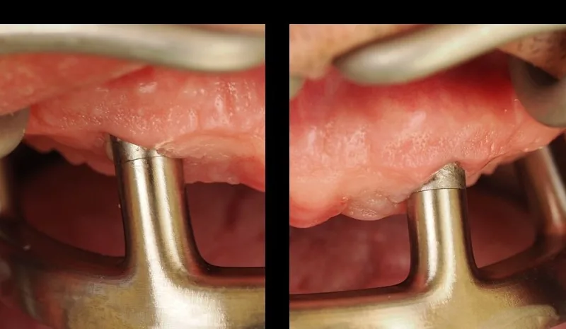
One-screw passive-fit check of a full-arch restoration – Sheffield test
Illustrative seating check of a full-arch restoration. Clinical interpretation belongs to the treating team's protocol.
verification prototypeverification jigverification frameworkprototype try‑in

A printable direct-to-MUA trial can answer a different question from the definitive prosthesis

If the library provides a direct-to-MUA PMMA/provisional branch, a physical prototype can be produced before definitive milling or printing. It can be used to assess seating on the MUA, screw-channel access, restoration volume, occlusion and, according to the clinical protocol, passive fit using, for example, the one-screw / Sheffield principle.

What this trial cannot do:by itself, it does not prove micrometre-level accuracy of the entire digital data pathway. It is a physical verification layer that can reveal clinically relevant rocking, incomplete seating or mismatch before definitive fabrication.

The same general principle of physical verification can also be used with animplant-level model before fabrication of a removable PSD restoration. In that workflow, however, the verification jig does not verify the definitive restoration or the position of the PSD attachments; it verifies whether the physical model reproduces the relative implant positions accurately enough to proceed safely.


Step 7 · definitive restoration

The final screw closes the workflow, but it cannot correct an error introduced earlier

After successful verification, fabricate the definitive restoration using the same library and component branch that was verified with the prototype. During final tightening, again distinguish the primary implant–MUA connection from the secondary restoration–MUA connection.

Primary connection: implant → MUA

Torque and instrumentation are determined by the exact MUA reference. Straight and angulated MUA may require different insertion methods and tightening torques.

  • verify the REF and current torque
  • check MUA seating
  • do not use a universal value based on “type”

Secondary connection: restoration → MUA

For the standard AB Multi-Unit RP Ø4.8, IPD specifies forIPD/AB‑TR‑00Unigrip and 15 Ncm. Other screws, including TPA/ASC variants, may require different instruments and rules.

  • AB‑TR‑00: Unigrip · 15 Ncm
  • ASC/TPA: use the specific screw, library and TPA instrument
  • final torque according to the exact REF
FAQ

Common points where the MUA workflow can break down

Is the same driver used for straight and angulated MUA?

No. A straight MUA uses an instrument for the external HEX 2.0, typically IPD/LL-AB-00. For angulated MUA with a primary Unigrip screw, use the corresponding Unigrip instrument. The exact MUA reference always takes precedence over a general rule.

Is there one recommended torque for all straight or all angulated MUA?

No. Current IPD product data vary between compatibility families. Before clinical use, identify the exact REF and verify the current value.

AB-SR-00 or AB-SR-01?

AB-SR-00 is engaging and transfers rotational orientation; AB-SR-01 is non-engaging. For splinted multi-unit restorations, a rotational/non-engaging logic is typically required, whereas an engaging branch may be relevant for a single crown if supported by the specific MUA and library.

When should AB-SR-11 Scan Transfer be used?

When reliable relationships between distant MUA positions are critical in a full-arch case and you want to work with a rigid physical reference pathway. Scan Transfer has its own protocols and corresponding library workflow.

TECH or LITE?

TECH is for IPD scan-body geometry. LITE is for supported OEM / third-party scan bodies. In both cases, the MUA level must actually have been scanned when designing on MUA.

Is “mock-up” the right term for a passive-fit trial?

For geometric verification, “verification prototype”, “verification jig” or “verification framework” is more precise. If the complete trial restoration is being tested in resin/PMMA, “prototype try-in” or “verification provisional” can be used.

Send us the implant system, exact MUA REF, scan body and CAD software.

We can help verify that the instrument, torque, engaging/non-engaging scan, TECH/LITE library, direct-to-MUA option and final screw form one consistent workflow.

Technical support

This technical web presentation does not replace the current instructions for use. For torque, sterilization, indications and compatibility, the exact reference and current manufacturer documentation always govern.

e-dent logo

I am a healthcare professional within the meaning of Section 2a of Czech Act No. 40/1995 Coll., on the Regulation of Advertising. I confirm that I am authorised to access pages intended for healthcare professionals.