
Exclusive IPD distributor for the Czech and Slovak RepublicsOriginal components · CAD/CAM libraries · technical support+420 604 483 343obchod@exklusiv-dent.cz
CLINICAL + LABORATORY PROTOCOL 20° / 40° KA-CL-14 Chairside pickup

From path-of-insertion diagnosis to prosthesis maintenance

IPD PSD attachments: clinical–laboratory workflow from impression to final retention

PSD / Locator® between clinic and laboratoryIPD Solutions Map · clinic ↔ laboratory

A practical map for the clinician and dental technician: establish the geometry and common path of insertion first, then select retention strength, transfer the position, process the titanium housings and only then install the definitive nylon inserts.

This page connects the IPD PSD System with the clinical principles of Locator®-compatible attachments. For component KA-CL-14 we follow the confirmed IPD workflow using three lengths: carrier, impression coping and scan abutment.

Core rule: divergence determines the insert family. The desired resistance to removal determines the retention strength. Higher retention does not compensate for an incorrect path of insertion.

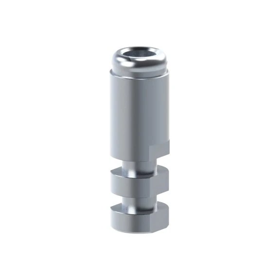
IPD KA-CL-14 as carrier, impression coping and scan abutment for PSD attachments
PSD processing pack KA-CL-02 for retention up to 20 degrees
KA-CL-02standard pathway up to 20°
PSD divergent processing pack KA-CL-03 for retention up to 40 degrees
KA-CL-03divergent pathway up to 40°
PSD titanium housing KA-CL-00 for a removable prosthesis
KA-CL-00housing in the prosthesis
Step 0

First determine where the PSD attachment level is created

The same retention logic can follow two different prosthetic pathways. However, components used for implant-level transfer must not be confused with components used at PSD sites created on a CAD/CAM framework.

Identify the implant system and platform.

Measure the gingival height and prosthetic space.

Establish one common path of insertion for the prosthesis.

Only then assess the divergence of the individual attachments.

PATHWAY A

PSD directly on the implant

Select the specific PSD abutment according to implant, platform and gingival height. Tightening torque is defined by the exact reference for that implant system; there is no universal torque for the entire PSD family.

Next assess divergence, select the 20° or 40° retention family and choose direct or indirect housing processing.
PATHWAY B

PSD attachments on a CAD/CAM framework

A primary framework or bar creates new retention sites and can compensate for part of the implant non-parallelism. The prepared threaded site receives PS-LR-00. Complete the framework stage on the dedicated page; once the PSD sites have been created, return here to select the 20°/40° family, process the housings and choose definitive retention.

Dedicated CAD/CAM workflow

Decision point 1

Geometry first: 20° or 40°?

IPD divides PSD retention inserts into a standard family for up to 20° total divergence and a divergent family for up to 40° total divergence. In practice, each attachment is assessed relative to the common path of insertion of the prosthesis.

STANDARD PATHWAY

KA-CL-02 · up to 20°

20°
IPD KA-CL-02 processing pack for total divergence up to 20 degrees
Processing pack for standard retention inserts. Typical geometric model: approximately 10° per side relative to the common path of insertion, corresponding to 20° between two attachments.
10°20° total10°
DIVERGENT PATHWAY

KA-CL-03 · up to 40°

40°
IPD KA-CL-03 divergent processing pack for total divergence up to 40 degrees
Divergent processing pack for greater angular discrepancy. Typical geometric model: approximately 20° per side relative to the common path of insertion, corresponding to 40° between two attachments.
20°40° total20°

Visual orientation: divergent inserts have a different central geometry without the standard central retention projection. Use this as an identification feature, not as the sole criterion for choosing the angular range.

How to manage multiple attachments

Assess every retention site relative to one common path of insertion for the entire prosthesis. If all attachments fall within the tolerance of the standard family, use standard inserts. If one attachment requires greater angular compensation, use a divergent insert for that site within the permitted range. There is no need to convert all other well-aligned attachments to the 40° family simply because one position is more angulated. With extensive or unmanageable non-parallelism, it is preferable to correct the prosthetic axis with the framework rather than rely on nylon flexibility to solve the entire problem.

Decision point 2

Only then choose retention strength

Retention should make the prosthesis feel secure in function while remaining realistically removable by the patient. With multiple attachments, resistance is cumulative, so start with the lowest clinically sufficient retention and increase it only if needed.

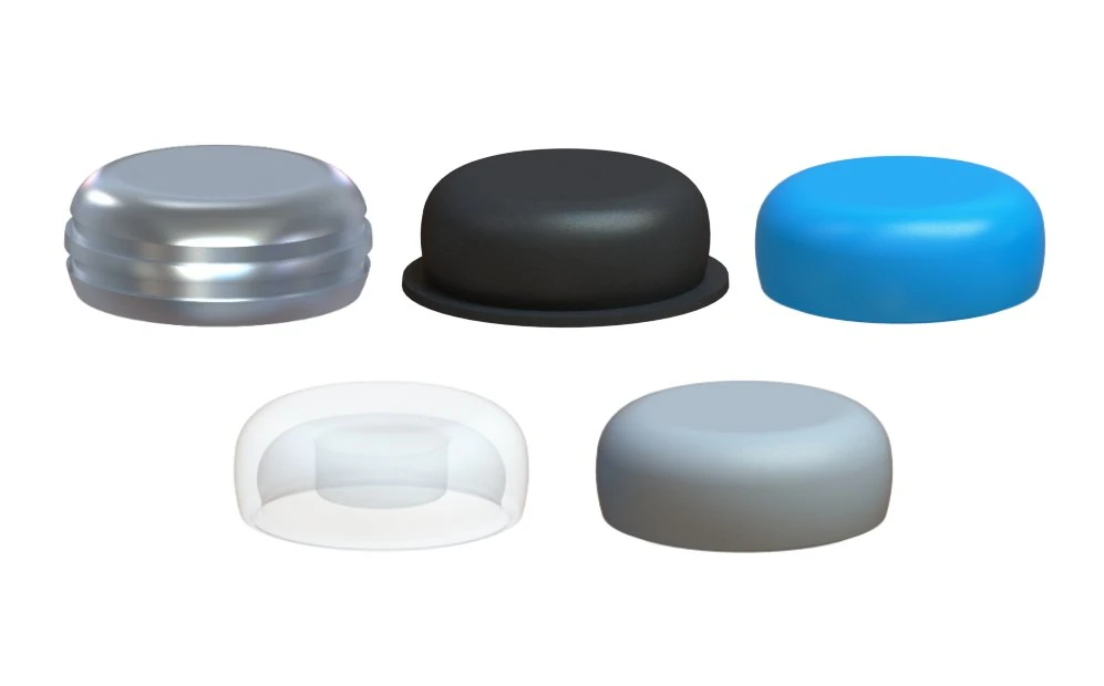
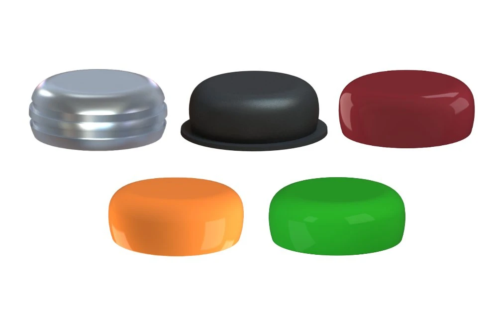
IPD PSD retention insert set KA-CL-01 up to 20 degrees
KA-CL-01 · mixed pack of standard retention inserts for the up-to-20° family. Select the actual retention strength only after the correct angular family has been established.
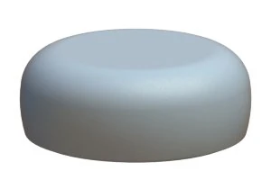
Grey IPD nylon retention insert KA-CL-11, 3 lb, up to 20 degrees
20°

KA-CL-11 · grey

3 lb
medium retention
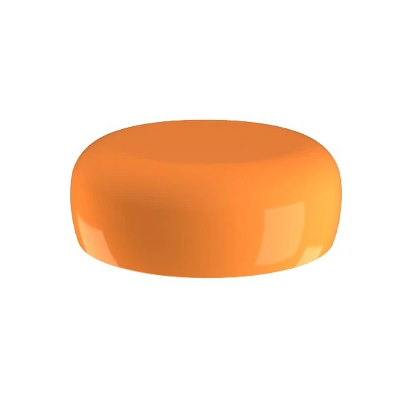
Orange divergent IPD nylon retention insert KA-CL-05, 2 lb, up to 40 degrees
40°

KA-CL-05 · orange

2 lb
medium retention

Start lower

For a new case, begin with the lowest retention that safely stabilises the prosthesis. The patient must be able to remove it repeatedly and in a controlled manner.

Attachment numbers add up

Four housings with high-retention inserts can create very different overall resistance from two housings. Do not choose strength by considering a single insert in isolation.

A stronger insert does not correct the geometry

If the prosthesis does not follow the common path of insertion or does not seat passively, address the axis, interferences and undercuts first. Increase retention only after the mechanics of the case are correct.

Decision point 3

KA-CL-14: one component, three lengths and three functions

The current IPD catalogue identifies KA-CL-14 as Carrier / Scan Abutment / Impression Coping. For practical processing, we follow the confirmed IPD shortening protocol based on the three grooves on the component body.

1KA-CL-14 at full length as a PSD attachment carrier

Full length · carrier

Without shortening it functions as the KA-CL-14 as carrier, a handling carrier for secure gripping and insertion of the PSD component.

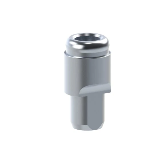
2KA-CL-14 after the first shortening as an impression coping, with two grooves remaining

1st shortening · impression coping

After the first shortening, two grooves remain on the body. At this length it serves KA-CL-14 as impression coping to transfer the PSD attachment position into a conventional impression.

3KA-CL-14 shortened at the third groove from the top as a scan abutment

3rd groove from the top · scan abutment

After shortening at the final, third groove from the top, a short reference geometry is created for digital acquisition, i.e. the scan abutment.

Shortening is an irreversible choice of length

Before you KA-CL-14 shorten it, decide whether you need a carrier, conventional impression coping or digital scan reference. The cut must be clean and must not damage the seating or reference geometry. Clean, disinfect and, where applicable, sterilise according to the current instructions for use for the specific reference.

Decision point 4

Three routes to a working model and geometry verification

This is not simply a choice between “stone versus 3D printing”. If an implant-level digital model was created before the definitive gingival height of the PSD attachments was known, a separate clinical model-verification step can sit between digital acquisition and the final attachment-level impression.

Route 1 · conventional impression

KA-CL-14 → PS-AR-00 → stone model

IPD analog PS-AR-00 for a stone PSD working model
Definitive PSD-level transfer. The attachments have already been selected clinically and their positions are transferred directly.
  1. Select and clinically seat the definitive PSD attachments.
  2. Shorten KA-CL-14 to the impression-coping length and verify complete seating.
  3. Take an accurate elastomeric impression.
  4. Connect PS-AR-00.
  5. Pour the stone working model and verify analog stability.
Route 2 · direct digital PSD pathway

KA-CL-14 → library → PS-AR-00/3D

IPD digital analog PS-AR-00/3D for a 3D-printed PSD working model
Definitive PSD-level digital model. The attachment type and gingival height must already be known.
  1. Seat the definitive PSD attachments.
  2. Scan KA-CL-14 in the scan configuration.
  3. Use the corresponding PSD library and verify correct matching.
  4. Create the model for PS-AR-00/3D.
  5. Validate the printing chain and the local seating of the digital analogs.
Route 3 · digital-to-analog verification

Implant-level model → verification jig → definitive PSD impression

This route is useful as an intermediate control step when an accurate implant-level model with system-specific digital analogshas been created, but the final gingival heights of the PSD attachments are not yet known with confidence.

  1. Print the implant-level model from validated scan-body + library transfer data and insert the correct implant-system digital analogs.
  2. Create a laboratory verification jig on suitable rigid reference components, for example Ti-bases.
  3. The clinician tries the jig intraorally and assesses passive seating on the actual implants. The purpose is to reveal clinically relevant discrepancies, not to claim micrometre-level agreement.
  4. After successful verification, determine the correct PSD attachment gingival heights clinically.
  5. Seat the attachments and transfer their definitive position with an elastomeric impression using the appropriate impression configuration. KA-CL-14.
  6. Create an attachment-level working model and continue with conventional fabrication of the prosthesis.
QuestionConventional PSD impressionDirect digital PSD modelImplant-level verification step
What is known at the time of transferdefinitive PSD attachments and their heightsdefinitive PSD attachments and their heightsaccurate implant-level reference; PSD heights may still need to be determined clinically
Primary referenceKA-CL-14 as impression copingKA-CL-14 as scan abutmentsystem-specific implant analogs + rigid verification components
What we verifyattachment-level transfer into stonePSD library matching + PSD model printingthe implant-level geometry of the model relative to the patient’s mouth
What followsconventional fabricationdigital / model-based fabricationPSD height selection → elastomeric PSD impression → conventional fabrication
Do not confuse with: the length or cuff height of the Ti-base used for the verification framework does not determine the height of the future PSD attachment. Here, the Ti-base serves only as a rigid reference element connected to the implant-level connection.

Extended digital pathway

Working model from an implant-level scan → KA-CL-14 → hybrid prosthesis design

This pathway is useful when accurate implant data are acquired with an intraoral scan, the working model is produced externally and the prosthesis is designed later in the laboratory. The key is to distinguish correctly between implant-level referenci and the subsequent PSD / Locator-compatible reference.

Do not confuse model levels

If the 3D model is designed at implant level,it must contain the system-specific digital analog for that implant. If the CAD workflow converts the known implant position to a precisely selected PSD attachment and the model is created directly at PSD level,it uses PS-AR-00/3D and an implant analog no longer needs to be physically present in the model.

1 · Implant-level input

The input IOS data must contain an exact scan-body reference. When an OEM scan body is used, only the library intended for that system, platform and specific scan-body geometry should be used; with a compatible IPD pathway this may be the corresponding LITE library.

2 · Reconstruct the implant coordinates

Matching the scan body to the library establishes implant position and axis. These coordinates are the primary geometric reference; an anatomical STL alone is not sufficient without validated scan-body transfer.

3 · Transition to PSD level

CAD must use the exact PSD attachment for the implant, including the correct gingival height. Only this known geometry can establish the coronal position of the Locator-compatible attachment and enable preparation of a PSD-level model.

4 · 3D model + PS-AR-00/3D

The model is printed with validated sockets for PS-AR-00/3D. After insertion, verify complete seating of the analogs, stability without play, and consistency with the selected library and print offset.

5 · Laboratory scan with KA-CL-14

Fully seat KA-CL-14 in the scan configuration on each PSD analog. The laboratory scanner records all references together with sufficient stable surrounding model geometry, and CAD matches them again to the PSD library.

6 · CAD design → manufacture → verification

Design the hybrid prosthesis from the confirmed PSD coordinates. Send the manufacturing data through a validated printing or other production chain; verify the completed prosthesis on the working model and finally in the clinic.

Implant-level model

Scan body → implant library → system-specific digital analog

This route physically reproduces the implant. To continue at PSD level, the corresponding physical PSD component must then be connected to the implant analog. PS-AR-00/3D is not a substitute for an implant analog.
Model created directly at PSD level

Implant coordinates → exact PSD reference → PS-AR-00/3D

If the CAD library supports this pathway and the PSD attachment type and gingival height are known precisely, the working model can be created directly for PS-AR-00/3D. The laboratory can then scan KA-CL-14 on the model and proceed directly to prosthesis design.
If the definitive PSD height is not yet known: do not convert the implant-level coordinates prematurely into a PSD-level model. Retain the implant-level model; it can be clinically verified with a rigid verification jig before the next stage, and only after confirming the geometry and assessing the soft tissues should the specific PSD attachments be selected. See digital-to-analog route A3.
Control condition: A LITE library is not a universal way to convert any OEM scan body to any IPD analog. The implant system, platform and scan-body geometry must match exactly. Likewise, converting implant-level coordinates to a PSD-level model requires a precisely defined PSD reference and gingival height.

Decision point 5

Chairside pickup: processing titanium housings intraorally

For direct intraoral processing, use the titanium housing KA-CL-00, the black processing insert KA-CL-13 and the block-out ring from processing pack KA-CL-02 or KA-CL-03. The aim is to pick up the housing in the prosthesis in its true intraoral position without allowing resin to lock the prosthesis into undercuts.

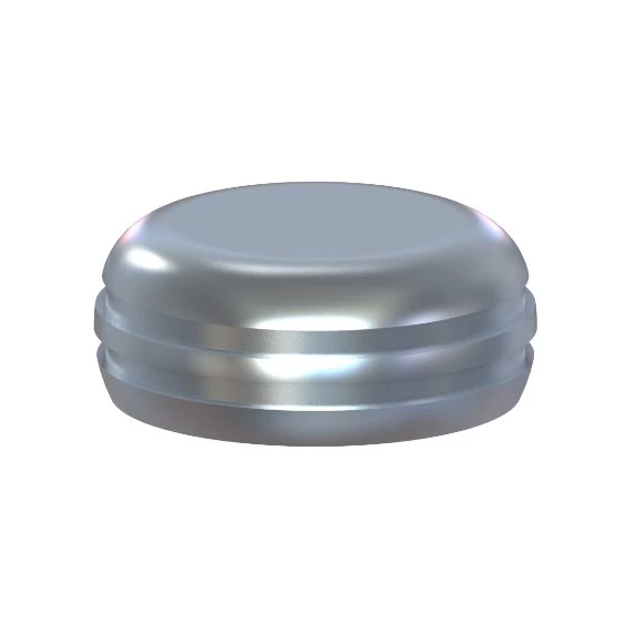
IPD titanium housing KA-CL-00 for chairside pickup
KA-CL-00 · titanium housing
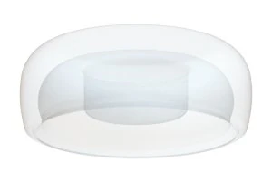
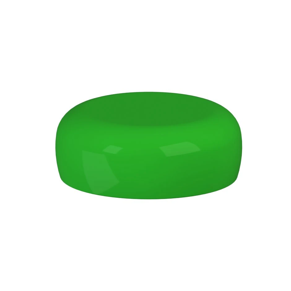
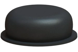
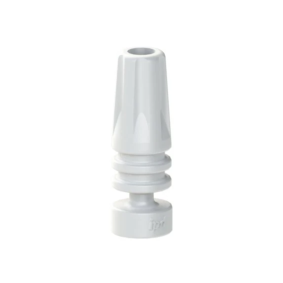
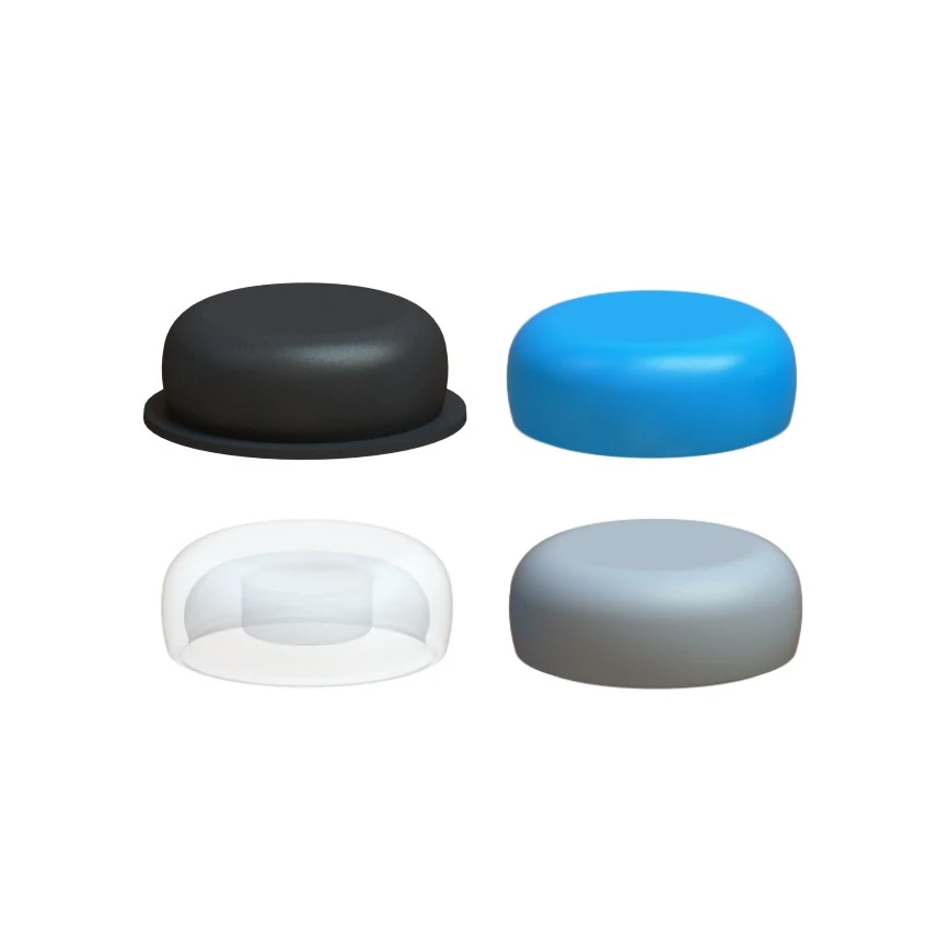
Black IPD processing insert KA-CL-13 for PSD polymerisation
KA-CL-13 · processing insert
Black KA-CL-13 is not definitive retention. It is a working insert for processing. The definitive nylon retention insert is installed only after polymerisation, finishing and polishing of the prosthesis.
1

Verify the attachments and common path of insertion

The attachments must be tightened to the correct torque and the surrounding area must be clean. Before pickup begins, the prosthesis should have a stable, repeatable position.

2

Seat the block-out ring down to the soft tissues

The spacer ring closes the undercut space around the attachment. During direct intraoral processing it acts as a safety barrier against resin flow and mechanical locking of the prosthesis.

3

Seat KA-CL-00 with the black KA-CL-13

The black processing insert remains in the titanium housing throughout processing. The housing must seat completely on the attachment and must not be tilted before polymerisation.

4

Create passive relief in the prosthesis

Mark where the housing contacts the intaglio and relieve material until the prosthesis seats completely without transferring pressure to the housing. If needed, create a vent hole to verify seating and allow excess resin to escape.

5

Apply the processing material according to its instructions for use

Place the material in the prepared recess or on the appropriate surfaces according to the selected chairside system. Minimise contamination of the retention mechanism and avoid excess material.

6

Seat the prosthesis in the correct occlusal position

Have the patient close into a reproducible occlusion without excessive force. The prosthesis must not shift from its final position during polymerisation. Follow the material manufacturer’s curing time.

7

Remove, remove the rings and finish the denture base

After curing, remove the prosthesis carefully, remove the block-out rings and excess resin, round the margins and polish the prosthesis. Verify that the housings are securely captured and that their internal surfaces have not been flooded with resin.

8

Only now replace the processing inserts with the definitive

Using LL-PS-01 remove the black KA-CL-13 and insert the selected definitive retention insert from the correct angular family. Verify that the insert snaps completely into the housing.

Decision point 6

Articulation and the second visit: chairside versus laboratory

The choice depends on whether you are simply converting an already functional prosthesis to PSD retention or fabricating a new prosthetic reconstruction with a new vertical dimension and tooth arrangement.

Chairside

Existing prosthesis with stable occlusion

If the prosthesis has verified occlusion, a stable base and the main change is the retention mechanism, the housing positions can be picked up directly intraorally.

Before pickup, verify seating of the prosthesis without the housings.

During polymerisation, guide the patient into a reproducible occlusion.

After polymerisation, check static and dynamic occlusion, pressure areas and the path of insertion.

Laboratory

New prosthesis or altered jaw relationships

For a new hybrid/removable prosthesis or when changing the vertical dimension, build a complete prosthetic workflow rather than allowing the pickup procedure itself to define the occlusion.

impression or digital model

occlusal rim and maxillomandibular relationship record

articulator mounting or digital articulation

setup / try-in, followed only then by final processing and retention

Practical key

Chairside pickup is excellent for accurately transferring the true intraoral position of the housings. It is not a substitute for occlusal records and articulation when tooth position, vertical dimension or jaw relationships are also being changed.

Decision point 7

Tightening torque: PS-LR-00 is 30 Ncm

The official IPD product page specifies for PS-LR-00, the PSD abutment/attachment intended for a CAD/CAM bar or framework, a tightening torque of 30 Ncm. Use the system-specific tool LL-PS-00 and a calibrated torque ratchet.

Avoid this mix-up: Do not automatically apply 30 Ncm to every implant-specific PSD abutment. For a PSD abutment connected directly to an implant, the prescribed torque may vary by implant system and reference.

Open the tightening-torque table
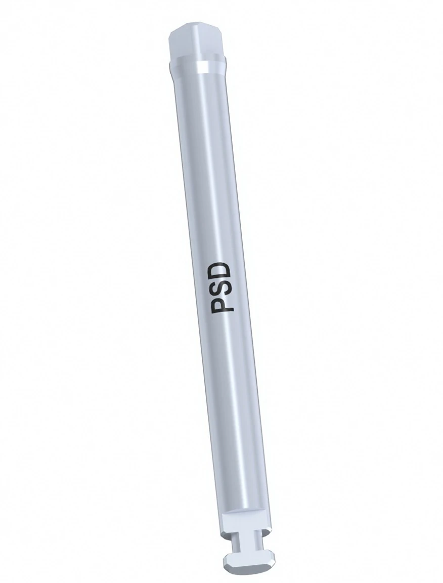
IPD PSD screwdriver LL-PS-00 for tightening PS-LR-00 to 30 Ncm
LL-PS-00 · system-specific PSD screwdriver. For PS-LR-00: 30 Ncm according to the current IPD product documentation.

Decision point 8

Delivery, maintenance and replacement of retention inserts

Definitive retention is a functional consumable element. At follow-up, assess not only the patient’s perception but also prosthesis seating, attachment wear, housing cleanliness, the patient’s ability to follow the path of insertion and changes in the soft tissues.

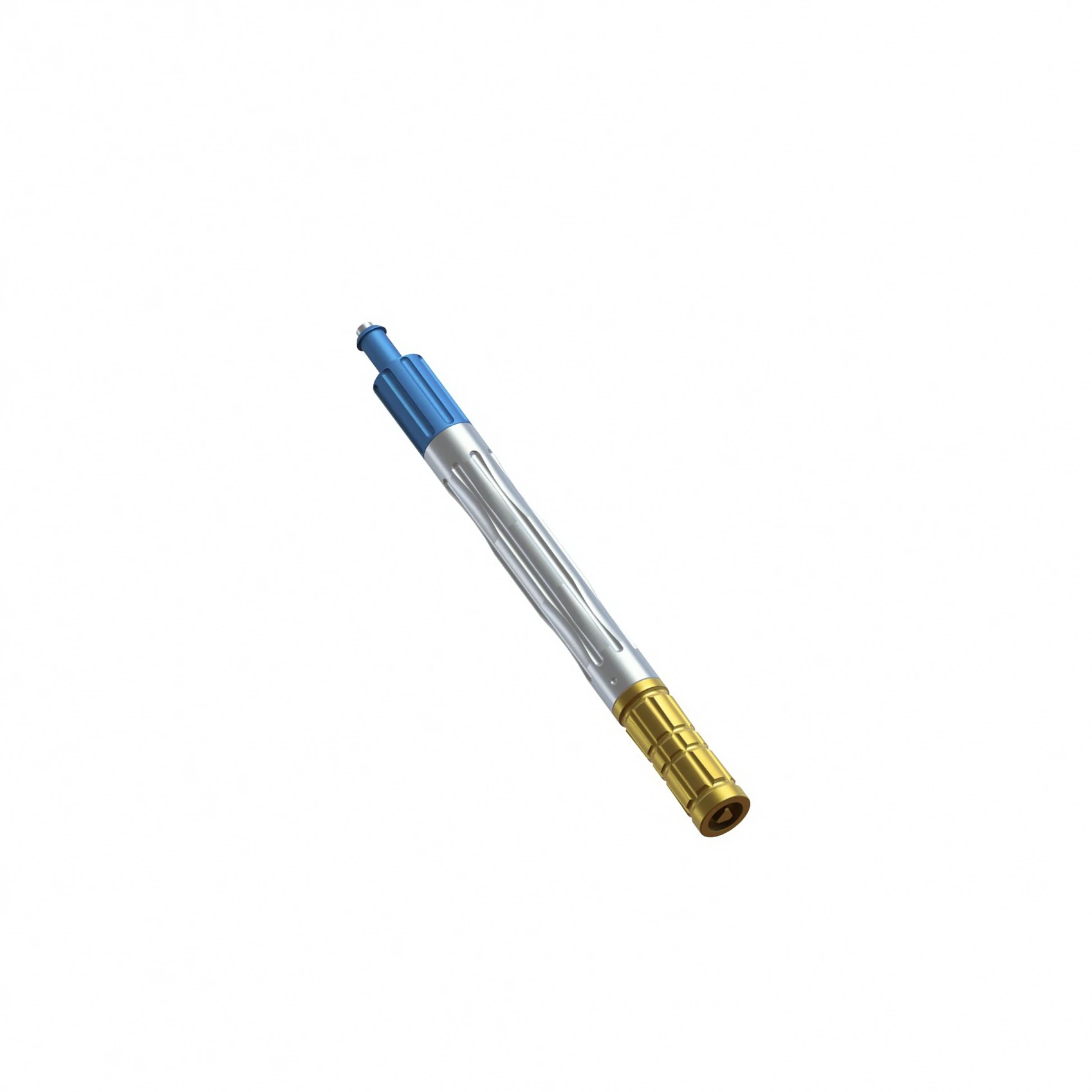
IPD tool LL-PS-01 for removal and replacement of PSD retention inserts
LL-PS-01 · tool for handling, removing and replacing PSD retention inserts.

Patient delivery

Have the patient insert and remove the prosthesis independently several times. If the force is excessive, adjust the retention level rather than forcing the path of insertion.

Replacing retention

Remove the existing insert LL-PS-01, inspect housing cleanliness and condition, and insert a new retention insert from the same angular family. Change retention strength only after clinical assessment.

When retention weakens too quickly

Look for divergence, an incorrect path of insertion, unilateral seating, a distorted housing, contamination or changes in prosthesis support. Simply installing a stronger insert may mask the cause.

Reline / rebase

During new laboratory processing, protect the definitive inserts. Use the black processing inserts during processing and install definitive retention only after finishing and polishing.

What to record in the patient documentation

Implant system and PSD abutment reference · gingival height · 20° or 40° angular family used · insert colour and retention strength · date of installation or replacement · any combination of retention strengths among individual housings.

The entire chain on one screen

From attachment to patient

Use this map as a quick check before a clinical or laboratory step.

KA-CL-14 for PSD position transferPosition transfercarrier / impression coping / scan abutment according to length
KA-CL-00 titanium housingHousingKA-CL-00 with a block-out ring and processing insert
KA-CL-13 black processing insertProcessingblack KA-CL-13 during polymerisation and finishing
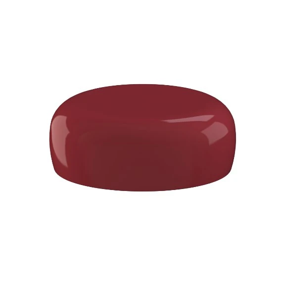
KA-CL-10 definitive blue retention insertDefinitive retention20° or 40° family with clinically appropriate strength

Control table

Quick decision by situation

When the case starts to branch, return to the sequence: axis → angular family → processing → retention strength.

Clinical situationSelectionWhy
Up to 10° on each of two attachments relative to the common path20° rodina
KA-CL-10 / 11 / 12
Total divergence up to 20°.
More than 10° but up to 20° at a specific attachment40° rodina
KA-CL-04 / 05 / 06
A divergent insert provides greater angular tolerance.
Four attachments and the patient struggles to remove the prosthesisreduce retention strengthOverall resistance is cumulative across multiple housings.
The prosthesis cannot be inserted along one pathdo not add retention forceFirst look for interference, non-parallelism or a seating error.
Direct intraoral processingblock-out + KA-CL-00 + KA-CL-13Protects undercuts and preserves the working state during the pickup procedure.
Conventional working modelKA-CL-14 impression coping + PS-AR-00Position transfer into stone.
3D-printed working modelKA-CL-14 scan + PS-AR-00/3DDigital position transfer through the library.
PS-LR-00 v CAD/CAM konstrukciLL-PS-00 · 30 NcmTorque specified by IPD for this exact reference.

Technical sources and level of certainty

What comes directly from IPD and what is a clinical principle

Product references, retention strengths, the 20°/40° ranges, PS-AR-00, PS-AR-00/3D, role KA-CL-14 and 30 Ncm for PS-LR-00 are supported by current IPD documentation. The detailed shortening sequence for KA-CL-14 is supplemented by the confirmed IPD workflow. Chairside processing is described as a general compatible-attachment principle and is always subordinate to the current IFU for the specific component and polymerisation material used.

IPD Product Catalogue 2026

PSD System workflow: KA-CL-14, PS-AR-00, PS-AR-00/3D, KA-CL-00, KA-CL-13, the 20°/40° retention strengths and processing packs.

IPD · PS-LR-00 product page

Official product reference PS-LR-00 and tightening torque of 30 Ncm.

IPD Shop · PSD Accessories

Reference summary KA-CL-00 through KA-CL-14, LL-PS-00, LL-PS-01 and PSD analogs.

Zest Dental · LOCATOR Attachment System

Reference geometric principle for the standard 20° and extended 40° families.

Zest Dental · LOCATOR direct processing technique

Reference chairside principle using a block-out spacer, black processing insert, housing pickup and subsequent installation of definitive retention.

FAQ for clinic and laboratory

Most common decision questions

Short answers to situations that are most often confused across the clinical–laboratory chain.

Yes, but only if the library chain is preserved. The implant-level scan must be correctly matched to the scan-body library; CAD must then know the exact PSD reference and gingival height. If the model is created directly at PSD level, PS-AR-00/3D is inserted and its position can be reacquired in the laboratory with KA-CL-14. If the model is created at implant level, it must use the system-specific implant analog; these two model levels must not be confused.
No. For the standard family, the working model is approximately 10° of correction on each of two sides relative to the common path, giving up to 20° total divergence between two attachments. For the divergent family it is approximately 20° + 20° = 40° total.
Not necessarily. Retention strength can be adapted clinically at individual retention sites, but only after each position has been assigned to the correct angular family and the common path of insertion has been verified.
No. The black KA-CL-13 is a processing insert. It is used during polymerisation and laboratory processing, then removed and replaced with the definitive nylon retention insert.
At full length it is a carrier. After the first shortening, with two grooves remaining, it functions as an impression coping. After shortening at the final, third groove from the top, it becomes the scan abutment configuration.
During direct intraoral pickup, place it around the attachment down to the soft tissues to close the undercuts and protect the surrounding area from polymerisation material. During laboratory processing, do not apply the ring automatically; follow the selected protocol and the current instructions for use.
No. IPD specifies 30 Ncm for PS-LR-00 when used in a CAD/CAM framework. For an implant-specific PSD abutment, use the torque specified for the exact implant system and reference.
When a specific attachment exceeds the standard angular tolerance relative to the common path of insertion but remains within the divergent range. If even the 40° family does not provide a controlled path, it is better to correct the prosthetic axis or framework rather than increase retention strength.

RELATED TECHNICAL PAGES

Choose the next step according to what you are solving now

The main PSD page covers the system, compatibility and components. The CAD/CAM page develops the bar/framework pathway with PS-LR-00. This page is the practical clinical–laboratory protocol.

Discuss a specific case

NEW DECISION HUB

Hybrid prosthesis on four implants: what should the clinician do and what should the laboratory do?

Start from the situation where you have an anatomical STL and need to choose between direct PSD attachments, a new KA-CL-14 scan or a CAD/CAM bar.

Open the decision workflow

Important information for use

Before clinical use: non-sterile device and correct component reference

PSD attachments, housings and accessories must match the implant system, platform and selected retention protocol.

  • Products are supplied non-sterile; follow the current instructions for use.
  • Verify gingival height, space for the housing and the appropriate retention insert.
  • Compatibility with the retention concept does not replace selection of the correct implant-specific reference.
e-dent logo

I am a healthcare professional within the meaning of Section 2a of Czech Act No. 40/1995 Coll., on the Regulation of Advertising. I confirm that I am authorised to access pages intended for healthcare professionals.