
What to measure
Prosthetic space, path of insertion, framework thickness, housing height and hygienic access.
CLINIC → LABORATORY → CAD → CAM → COMPLETION
A complete map of the workflow, from transfer of the initial implant positions through design and milling of the primary framework to precise placement of the PSD attachments, housings and definitive retention inserts.
This pathway is particularly useful when implant axes differ substantially and the nylon inserts alone would otherwise have to compensate for too much angulation. A CAD/CAM framework can create a more controlled common path of insertion, but only after verifying the available space, material requirements and exact geometry of the threaded sites for IPD/PS-LR-00.
Technical guidance, not a substitute for the instructions for use: Always verify the specific platform, component, thread geometry, tightening torque and retention range in the current IPD instructions and in the documentation for the specific framework.
PSD IN THREE LAYERS
A typical trigger is substantial implant non-parallelism, where it would be inappropriate to leave the entire geometric compensation to the resilience of the retention inserts. The framework creates new, planned positions for the PSD attachments.
Outer or otherwise problematic sites are markedly angulated relative to one another.
There must be room for the framework, retention head, housing and prosthetic material.
The geometry must come from current IPD data and documentation, not from an illustration.
Prosthetic space, path of insertion, framework thickness, housing height and hygienic access.
The correct platform, library, product codes, analog and continuity of the CAD data chain.
A passively seating framework with precisely planned retention sites aligned along a favourable common path of insertion.
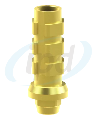
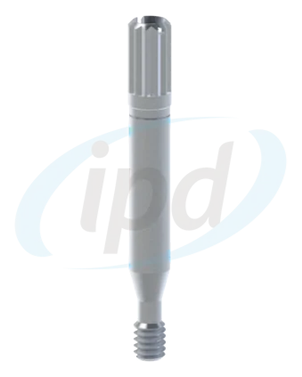
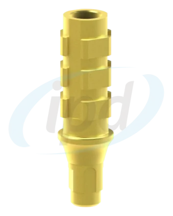
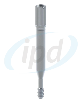
First obtain a reliable working model or validated digital data. In this framework pathway, the initial implant-level or Multi-Unit-level position is transferred using the corresponding system-specific impression component and long screw. KA-CL-14 is a multifunctional PSD component; its impression function belongs to the PSD-level workflow, whereas on this page its shortened scan configuration is used later to digitally transfer the PSD sites on the completed framework.
PATH A · CONVENTIONAL IMPRESSION
Always select one system-matched pair. DAPR06 and DBPR06 are alternatives for different platforms, just as DATR01-C and DBTR00-C are. Components are selected according to the specific implant or abutment level, not by visual similarity.
PATH B · DIGITAL INPUT
For digital input, confirm the correct scan body, library, complete seating and sufficient capture of the surrounding geometry. The result must provide an equally reliable starting position for framework design.
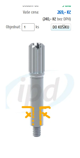
PHASE 1 OUTPUT
Each platform and position is clearly identified.
The model preserves the soft tissues and the space required for framework design.
Any required verification of the full-arch transfer has been resolved before CAD design.
The primary framework or bar absorbs the non-parallelism of the original implants and creates new retention points along a common axis. Accuracy at this stage underpins the entire downstream workflow.
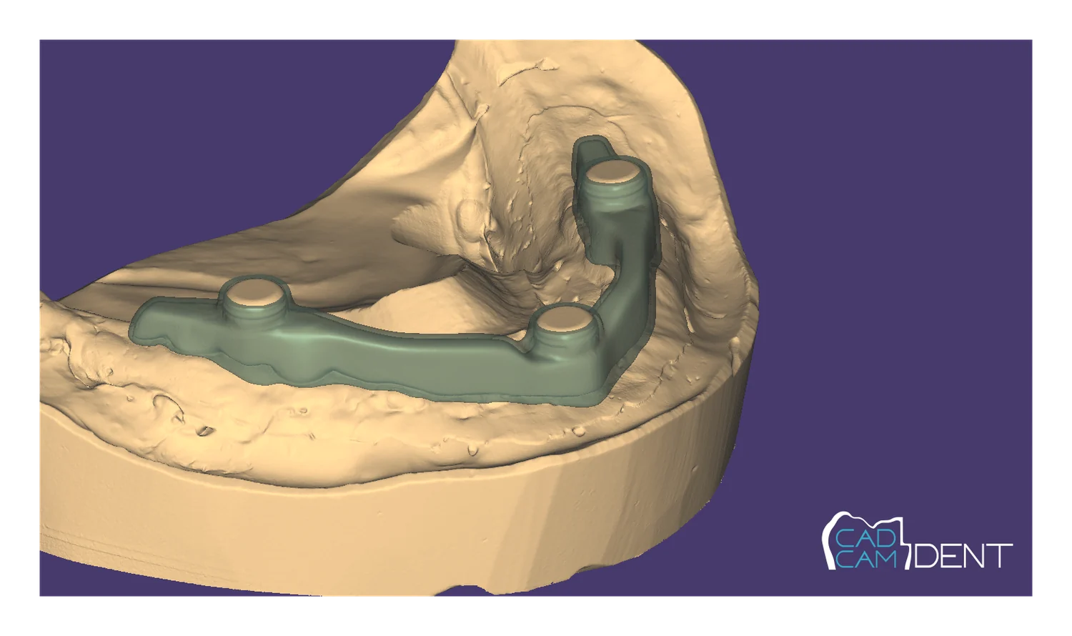
The new PSD-site axes should remain clinically and technically accessible and must not create an unmanageable undercut conflict.
Diameter, depth, seating surface and thread must comply with the manufacturing documentation PS-LR-00. The illustration is for orientation only and is not a manufacturing drawing.
After CAM manufacture, inspect the threads, seating surfaces and channel cleanliness before installing any PSD component.
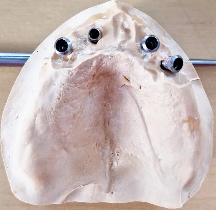
Passive fit: a scan body cannot correct a framework that does not seat correctly.
Vertical space: verify not only the attachment head but also the housing and sufficient prosthetic material around it.
Instrument access: all screw channels and retention sites must remain accessible.
Thread geometry: each site must be clean, undamaged and dimensionally verified.
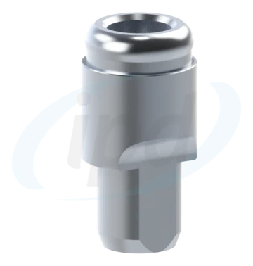
Only at this stage does KA-CL-14 enter the workflow in its shortest scan configuration, after shortening it at the last of the three grooves from the top. It records the positions of the retention sites created in the framework and transfers them into the digital working model. All three lengths KA-CL-14 are described in the clinical-laboratory protocol.
Use the configuration shortened at the last of the three grooves from the top. The reference geometry must be clean, undamaged and gap-free; verify seating visually and against the framework, not only from the software display.
Capture not only the scan body but also stable framework surfaces. These help verify matching and the relative position of multiple sites.
The component code, library file and analog must form one consistent chain. After matching, inspect the perimeter, height and orientation features.
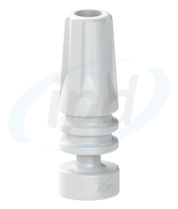
PHASE 3 OUTPUT
In the digital pathway, use PS-AR-00/3D. The model is used to verify housing space, matrix positions and laboratory completion. Before final printing, verify dimensional calibration and complete seating of the digital analog.
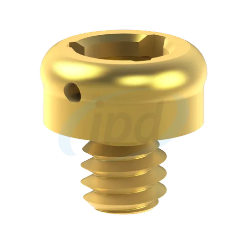
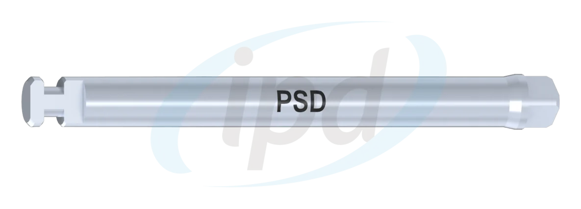
PS-LR-00 tighten with the system-specific instrument LL-PS-00 to 30 Ncm. This value applies to PS-LR-00 in the CAD/CAM framework; do not automatically apply it to implant-specific PSD abutments, for which torque is determined by the specific reference.
The housings must have sufficient space within the prosthesis and must not be forced into an unfavourable position. Block-out spacers protect the surrounding undercuts during pickup.
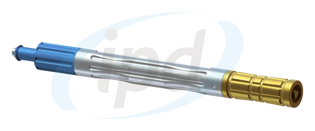
Black processing inserts remain in the housings during polymerisation and laboratory try-ins. Definitive retention inserts are placed only after finishing and polishing.
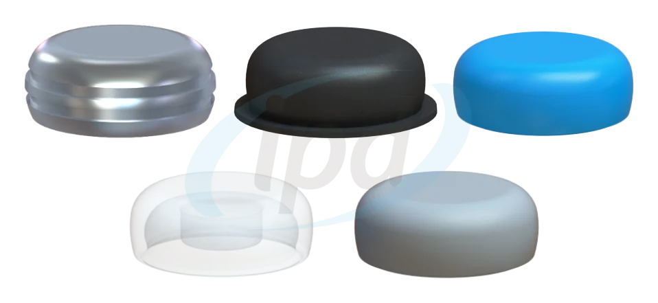
STANDARD FAMILY · TOTAL DIVERGENCE UP TO 20°
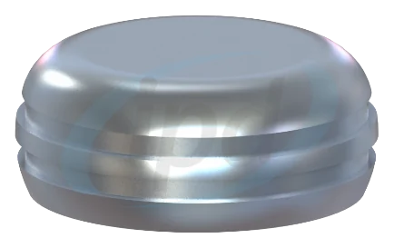
The processing pack contains a housing, block-out spacer, black processing insert and definitive inserts. The standard family corresponds to approximately 10° + 10° relative to the common path of insertion.
DIVERGENT FAMILY · TOTAL DIVERGENCE UP TO 40°
The pathway for greater non-parallelism, approximately 20° + 20° relative to the common path of insertion. If even this range does not provide an unimpeded path, correct the prosthetic axis or framework rather than increasing retention force further.
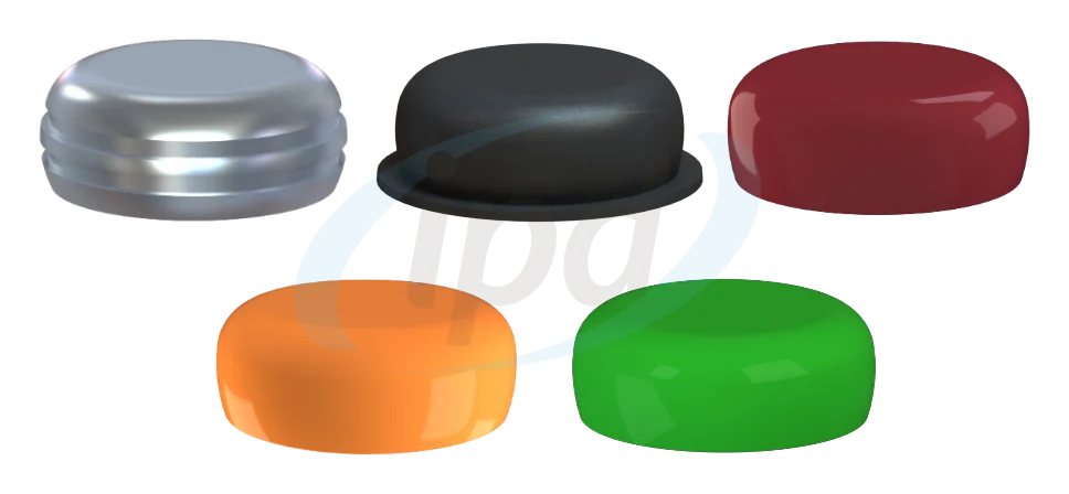
Use four complete processing packs, one for each attachment. The black processing inserts remain in the housings during polymerisation, keeping the definitive inserts unused. Spare inserts are better managed as a separate service pack than by purchasing additional complete housings.
COMPONENT CHAIN
The most common error is not the component itself, but using it at the wrong stage. This map shows how the individual parts actually connect.
Conventional transfer of the initial position according to platform.
Long screw corresponding to the selected impression coping.
Creates the common axis and precise threaded sites.
Digital registration of the retention-site positions on the framework.
Digital analog for the 3D-printed working model.
Definitive retention attachment screwed into the framework.
Housing incorporated into the removable prosthesis.
Processing inserts and definitive retention inserts.
Handling and replacement of nylon retention inserts.
QUICK CHECK
Five questions that catch most expensive dead ends before milling or printing.
Is the platform of every implant or abutment clearly identified?
Is there sufficient vertical and horizontal space?
Does the laboratory have the manufacturing geometry for the threaded sites PS-LR-00?
Do KA-CL-14, library and PS-AR-00/3D belong to the same system reference chain?
Is the use of black processing inserts planned before the definitive retention inserts?
RELATED TECHNICAL PAGES
The main PSD page explains the system and retention options. The related pages cover scan bodies, digital analogs, Multi-Unit components and accuracy control within the digital workflow.
NEW DECISION HUB
Start from the situation where you have an anatomical STL and need to choose between direct PSD attachments, a new KA-CL-14 scan or a CAD/CAM bar.
Important information for use
PSD attachments, housings and accessories must match the implant system, platform and selected retention protocol.
I am a healthcare professional within the meaning of Section 2a of Czech Act No. 40/1995 Coll., on the Regulation of Advertising. I confirm that I am authorised to access pages intended for healthcare professionals.