

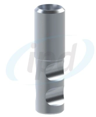
Analog
Implant analog
Physical replica for a conventional laboratory model.
This interactive workflow connects the analog or implant, scan body, crown or bridge Ti-base, cutting guides, drivers and the final fixation-screw selection.
The page converts the workflow diagram from the IPD 2025 catalogue into an interactive web format. It preserves the distinction between the anti-rotationalengagingand rotationalnon-engagingbranches while adding explanatory guidance, height options and product visuals.
A solid line shows the main production flow. Dashed connections indicate supporting instrumentation used across both branches.
Physical replica for a conventional laboratory model.
The reference connection that determines compatible components throughout the assembly.
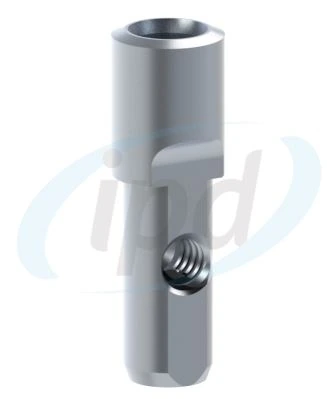
Replica for a digitally designed and 3D-printed working model.
An indexed connection with a defined orientation, intended primarily for single crowns.
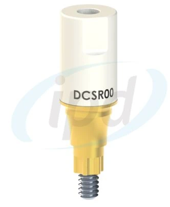
10 or 15 mm height depending on availability and the scanning situation.
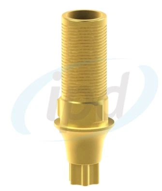
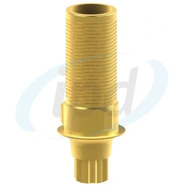
Custom Ti-base for N/R/W platforms, with indexing and three supplied gingival heights.
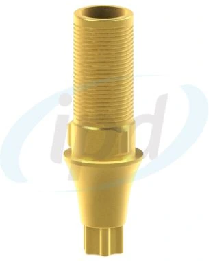
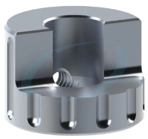
Cutting guide for controlled shortening to 6.5 / 5.0 / 3.5 mm and verification of the angulated screw channel.
The physical height must match the option selected in the CAD library.
A non-indexed option intended primarily for bridges and restorations splinting multiple implants.
10 mm height, with the correct library and complete seating maintained.
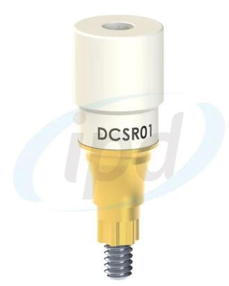
Non-indexed Custom Ti-base for N/R/W platforms and bridge restorations.
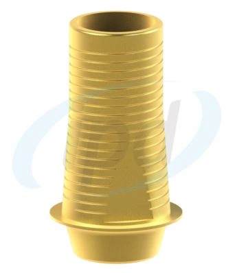

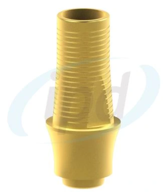
Cutting guide for controlled shortening to 6.5 / 5.0 / 3.5 mm in the rotational branch.
The resulting height and geometry must match the design and the selected library option.
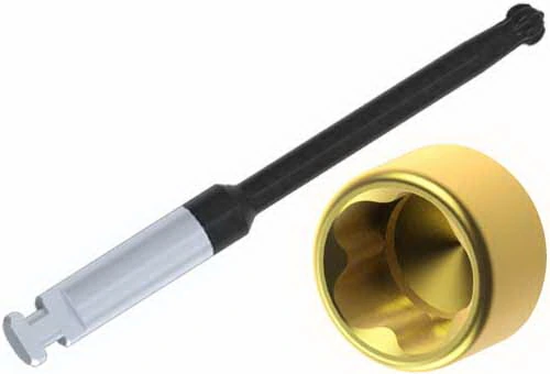
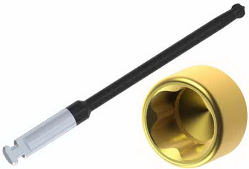
The supplied product set contains nine cutting-guide visuals. They are arranged below as a platform × height matrix to make selection faster than in the static catalogue.
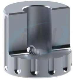
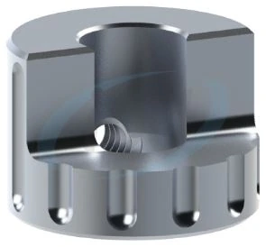
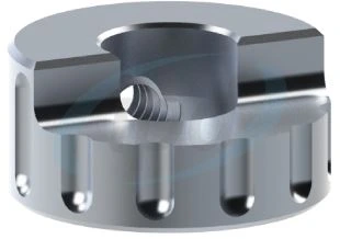
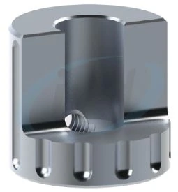
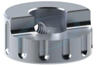
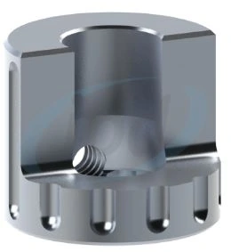
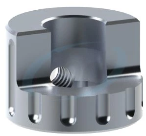
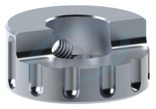
The height selected in the CAD library, the physical Ti-base height after shortening and the available space for the adhesive joint must remain consistent with one another. The specific procedure is governed by the current instructions for use and the technical specifications of the relevant system.
The workflow functions as a chain. Every selection must correspond to the same implant platform and the same CAD-library branch.
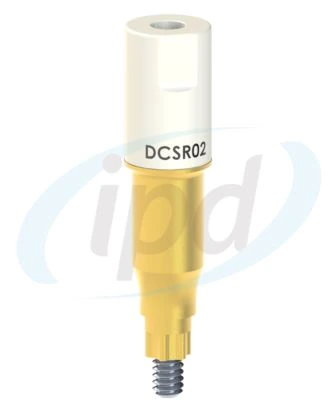
Choose the engaging or non-engaging scan body and the correct height so that the scan body is fully visible and safely accessible.
A single crown typically uses anti-rotational indexed geometry. A bridge or splinted restoration uses the rotational non-indexed option.
The supplied set shows 0.5 / 1.5 / 2.5 mm cuff heights for both single-unit and bridge options.
The cutting guide must match the platform and the target height of 6.5 / 5.0 / 3.5 mm.
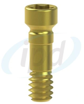
This choice determines the fixation screw, driver tip and access path. TPA availability must be verified for the specific system and platform.
| Decision | Anti-rotational branch | Rotational branch | Shared verification |
|---|---|---|---|
| Indication | Single screw-retained crown | Bridge or splinted restoration | Implant platform and CAD library |
| Scan Body | Engaging h. 10 / 15 mm | Non-engaging h. 10 mm | Complete seating and the correct driver |
| Ti-base | Indexed, cuff 0.5 / 1.5 / 2.5 mm | Non-indexed, cuff 0.5 / 1.5 / 2.5 mm | Physical component must match the CAD design |
| Cutting guide | Engaging cutting guide | Non-engaging cutting guide | N/R/W platform and 6.5 / 5.0 / 3.5 mm height |
| Fixation | Ti / TiN / BLC or TPA according to the indication | Correct tightening torque according to the instructions for use | |
The answers translate catalogue terminology into practical workflow language.
Engaging is an anti-rotational option with a defined orientation in the implant connection. Non-engaging is a rotational, non-indexed option suitable for restorations splinting multiple implants.
CAD software assigns position and connection type according to the library geometry. Mixing engaging and non-engaging components or platforms can lead to an incorrect design, screw-channel position or physical incompatibility.
They provide a mechanical reference for controlled shortening of the Ti-base chimney and, for the relevant options, guidance when preparing an angulated screw channel.
No. TPA availability, the permitted angulation range, fixation-screw type and driver tip vary by implant system, platform and specific Ti-base. The technical specifications must be checked.
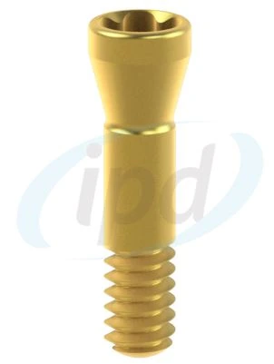
These are catalogue variants of fixation screws. The specific material and surface finish are selected according to the available reference and the manufacturer's technical documentation.
No. This page is an educational overview of the workflow. Cleaning, sterilisation, mechanical modification, cementation and tightening torque must always follow the current instructions for use for the specific component reference.
Send us the implant brand, platform, restoration type and CAD software you use. We can verify the scan body, Ti-base, CAD library, cutting guide, fixation screw and suitable driver.
Workflow source: Catalogue 2025, Custom Ti-Base System® – Workflow Diagram. Product visuals: supplied package “schema-upravitelne-ti-baze-ipd.zip”. The HTML page preserves the catalogue logic and adds a practical explanatory layer.
Restoration verification on the working model
After modification and restoration design, the working model is an important verification point. The analog must match the same platform as the Ti-base and the selected model-production workflow.

I am a healthcare professional within the meaning of Section 2a of Czech Act No. 40/1995 Coll., on the Regulation of Advertising. I confirm that I am authorised to access pages intended for healthcare professionals.