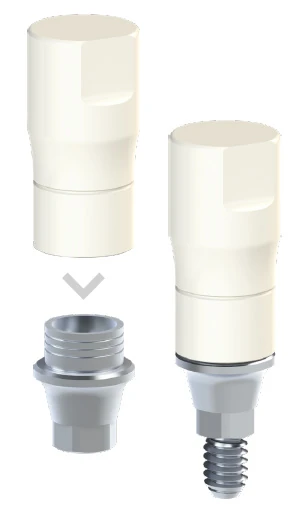
Base and burnout coping
Core principle: the metal Co-Cr base forms the implant interface, while the coping provides modelling freedom for wax-up and subsequent casting.
Wax-upBurnoutScrew-retained
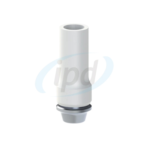
The IPD solution combines acobalt-chromium basewith aPOM / Delrin burnout copingfor waxing and casting. It supports straight and angulated screw channels, matches the selected implant system and helps carry interface accuracy into the laboratory restoration.
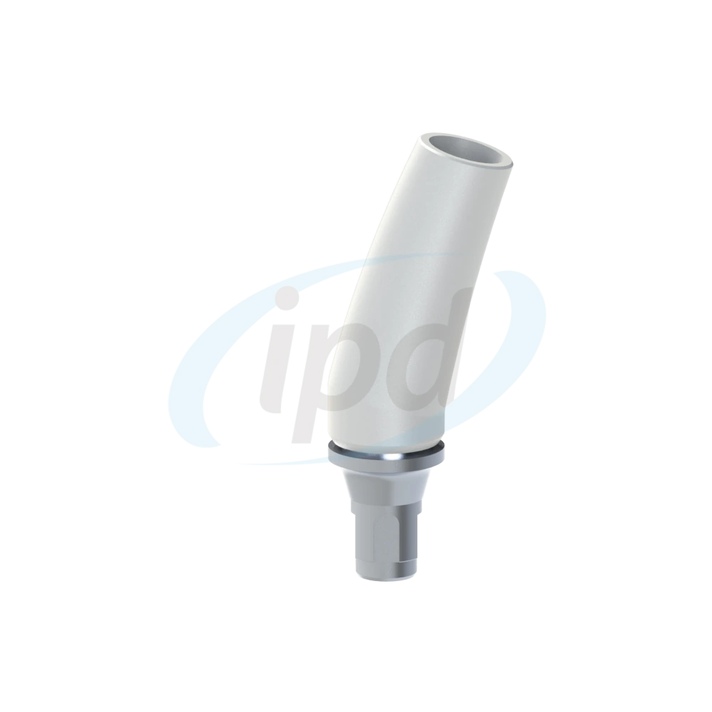
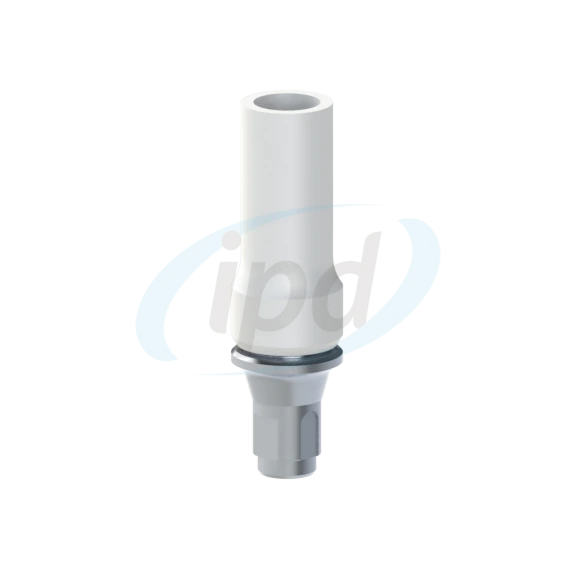
IPD cobalt-chromium bases combine aprecise metal interface a burnout copingfor laboratory waxing, casting or a hybrid CAD/CAM workflow. The supplied CREAS EN product presentation highlights three core benefits:versatility, reliable integration in both conventional and digital workflows a time efficiency. In practice, this means less improvisation in the critical implant-interface zone and a more predictable transfer from design to the definitive restoration.
Instead of one oversized detail, this section uses smaller, clearer illustrations from the supplied materials. Each card explains a different part of the workflow, from the base and burnout coping to the scan body and CAD library.
Core principle: the metal Co-Cr base forms the implant interface, while the coping provides modelling freedom for wax-up and subsequent casting.
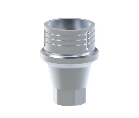
A clear view of the component that transfers interface accuracy into the entire restoration. Platform compatibility, complete seating and stable anti-rotation are critical here.
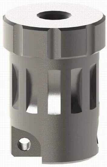
The detail illustrates the working zone of the base where the laboratory controls seating and the transition to the restoration. The source material also highlights a 1.8 mm vertical height for subsequent welding or joining of the metal framework.
The “Co-Cr Base” product card centres on three themes: versatility, reliable integration and time efficiency. Here they are translated into practical value for both laboratory and clinic.
Compatibility with different workflows and prosthetic solutions gives the laboratory greater flexibility in both workflow and manufacturing strategy.
IPD highlights optimised accuracy in both digital and physical environments. This matters whenever CAD design alternates with physical verification on the working model.
An efficient component design simplifies clinical and laboratory steps, reduces improvisation and helps keep the workflow predictable.
When the laboratory or clinic needs to transfer the position of a cobalt-chromium base into CAD, the workflow relies onscan bodies a IPD CAD libraries. In the supplied CREAS EN brochure, the scan body is presented as a solution forsingle and multiple-unit structureswith an emphasis onprecision, fit and reliabilityand compatibility with both chairside and laboratory systems.
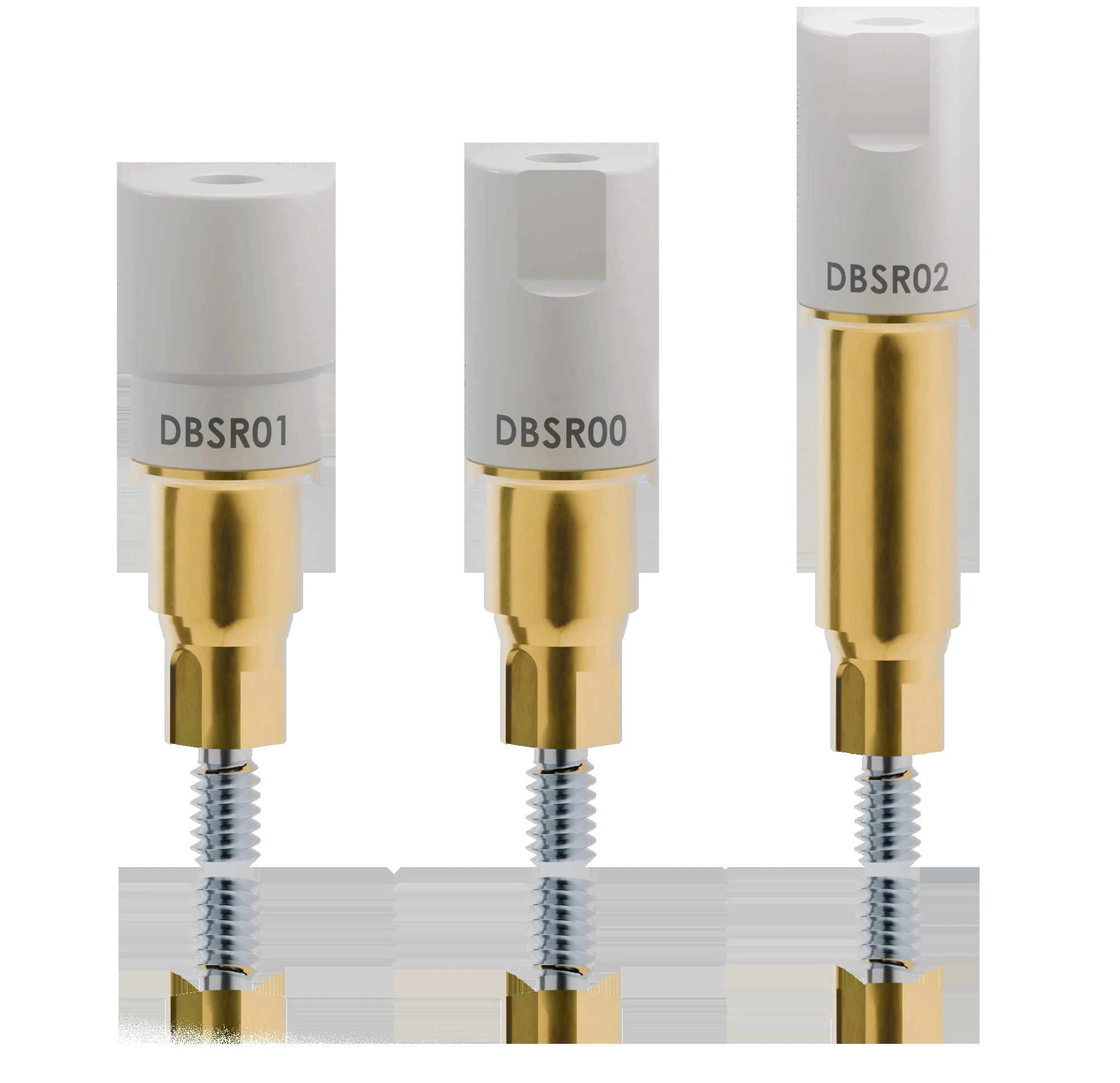
When the appropriate libraries are available for the base and implant system, the laboratory can scan the base positions, assign the correct STL components and design the restoration without manually approximating the interface. From a workflow perspective, this makes the transition from a conventional base to a digitally defined component much clearer.
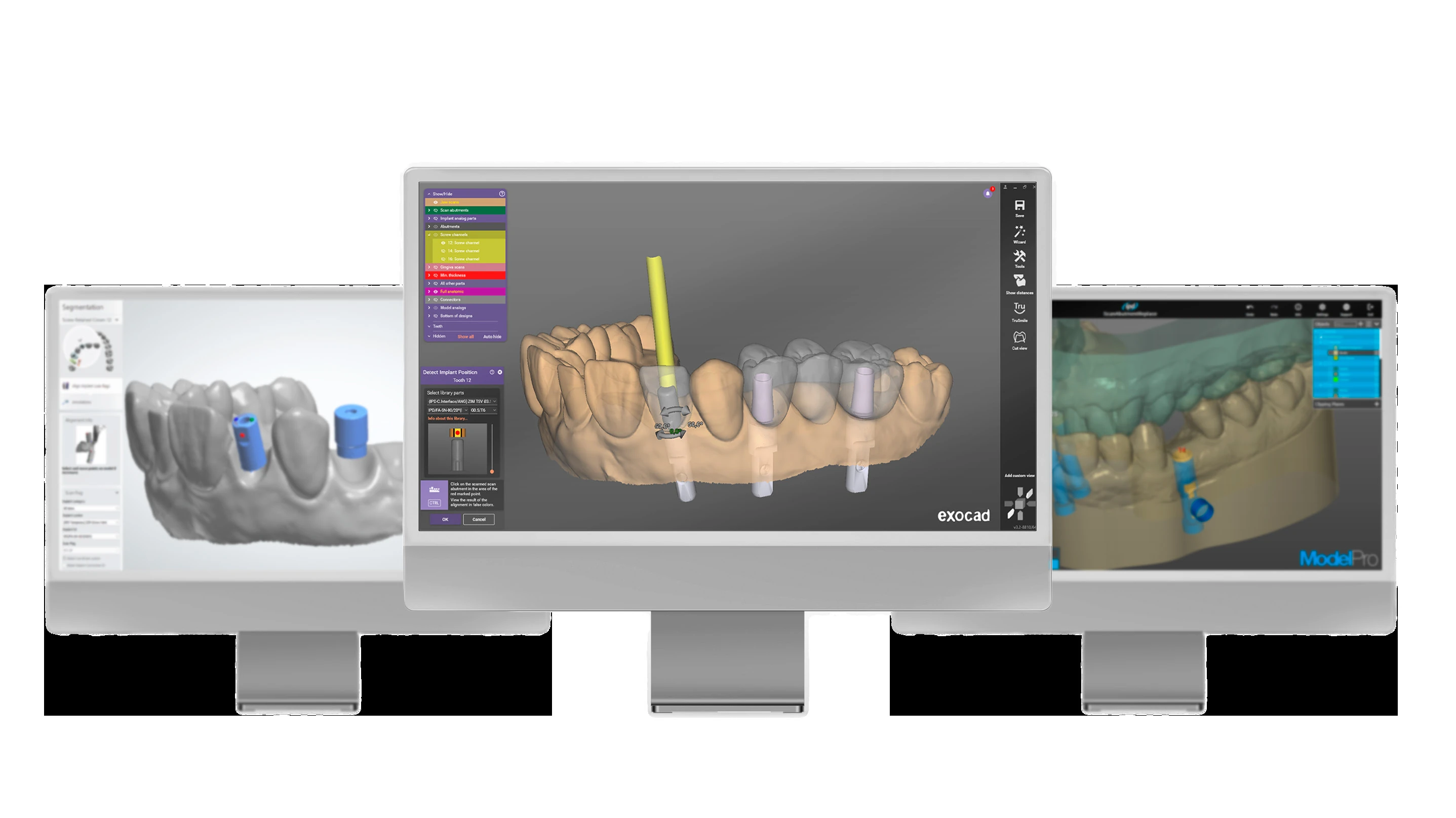
TECHis described in the brochure as a high-resolution STL library with optimised, validated ASC options and two cement-gap settings for individualisation.LITEis designed for simpler workflows with standard resolution, simplified ASC options and a default cement gap. The important point for users is that a “library” is not merely a file. It directly shapes how accurately and efficiently the technician can work in CAD.
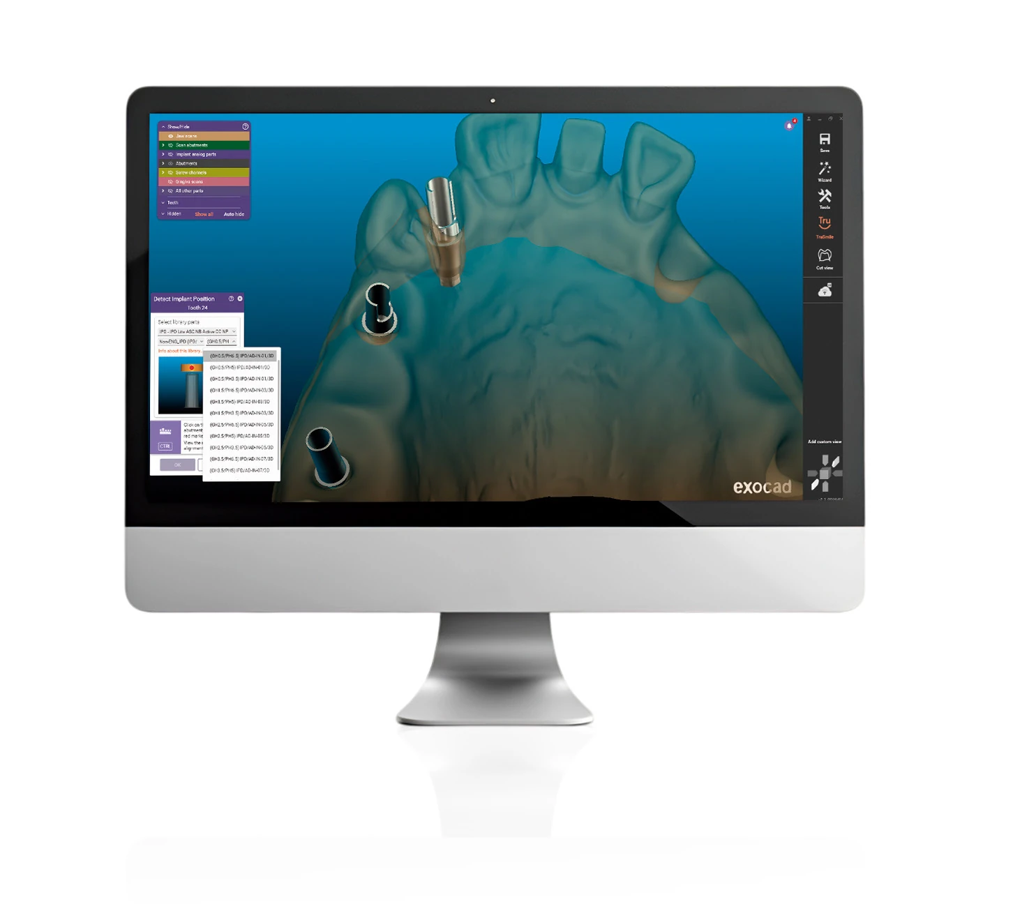
This illustration from the supplied brochure shows why CAD libraries matter in practice: the technician is not working “blind”, but with a defined component, its axis and the correct library selection. This improves confidence when designing the restoration, checking the path of insertion and preparing for manufacture.
The sequence below connects conventional and digital scenarios so that the laboratory and clinic can see when to use a scan body, when to work from a CAD library and when to proceed with conventional casting or metal milling.
First verify the implant platform, prosthetic space, emergence profile and screw-channel direction. Decide whether a straight or angulated Co-Cr base is more appropriate and whether the restoration will follow a predominantly conventional or hybrid digital workflow.
Seat the base on the implant or analog and decide whether to continue with a wax-up or first capture its position digitally. This is the point at which you choose between the burnout coping and a scan-body plus CAD-library workflow.
If libraries are available for the selected system, scan the base positions, assign the correct STL files and design the restoration in CAD. Library quality and the correct choice between TECH and LITE matter at this stage.
One common route starts with a CAD design or wax-up, followed by wax milling, investing, Co-Cr casting and final finishing. After casting, sandblasting is followed by careful verification of the interface and passive fit.
The second route uses metal milling of the suprastructure followed by welding or another laboratory joining process to the 1.8 mm vertical section of the Co-Cr base. Control of distortion, joint accuracy and passive fit is critical throughout this pathway.
Complete the restoration by checking proximal contacts, occlusion, aesthetics and access to the screw channel. Angulated channels use TPA fixation screws with a pentalobular drive and the corresponding RA system instruments.
For both straight and angulated Co-Cr restorations, the restoration must not only be manufacturable but also safely screw-retained and serviceable later. This section therefore explains the TPA concept in practical terms.
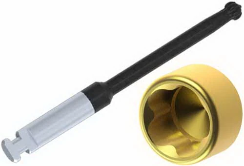
The illustration shows the type of system driver used for the TPA / ASC concept. The source material specifies lengths of18, 25 and 32 mm, helping the clinician select the instrument according to intraoral access and the spatial constraints of the restoration.
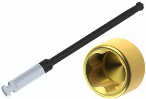
A longer RA / TPA driver improves access to deeper screw channels and when working through larger bridge frameworks. Driver length is therefore not a minor detail; it can materially affect clinical access and handling.
The supplied material specifies anRA-type adapter with a right-angle notch in the shankfor connection to a torque wrench with a 7 mm eye, or less commonly 8 mm. A specific C1030 illustration was not included in the supplied files, so the component is described here in text. The card can be extended with a visual detail when an image becomes available.
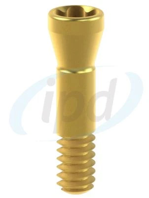
Illustrative screw for angulated channels with apentalobular screw-head drive. This screw type is essential when the access direction must be corrected while retaining secure screw fixation of the restoration.
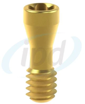
The second illustration shows the same principle for a tissue-level solution. These screws are not merely consumable parts: they directly influence serviceability and the options available when working with an angulated screw channel.
The page is prepared to embed the videoproteticke-komponenty-chrom-kobaltove-baze-ipd.mp4from the/videosfolder on proteticke-komponenty.cz. The video provides a practical complement to the written workflow and technical product presentation.
/videos/proteticke-komponenty-chrom-kobaltove-baze-ipd.mp4and optionally add a poster image.Detailed answers for laboratories, clinics and CAD/CAM partners, including CAD libraries, scan-body workflows and TPA screws.
An angulated base is useful when the screw-channel exit must be redirected for aesthetics, screw access or the space available within the restoration. Combined with a TPA fixation screw, it gives both laboratory and clinician more practical service access.
The coping is used for modelling and waxing. The product materials describe it as a burnout component designed to leave no interfering residue, which is important for clean investing, casting and subsequent finishing of the Co-Cr framework.
Yes. When the corresponding scan bodies and CAD libraries are available, the base positions can be scanned, the correct library assigned and the restoration designed in CAD. The next stage can be either wax milling followed by casting, or metal milling followed by joining to the base.
TECH libraries are designed for more detailed work, with high-resolution STL geometry, validated ASC options and multiple cement-gap settings. LITE libraries simplify the workflow and can suit users who prefer a faster, less complex setup.
In laboratory practice, the restoration can be designed and then produced by metal milling, followed by welding or joining to the Co-Cr base at its 1.8 mm working vertical height. Control of distortion, passive fit and protection of the interface during joining are essential.
TPA fixation screws with a pentalobular drive allow the restoration to be secured through an angulated screw channel, typically at angles up to 25°. This extends access options when a straight screw channel would be clinically or aesthetically unfavourable.
Check the implant system, platform, prosthetic space, required emergence profile, straight or angulated screw-channel option, laboratory workflow, library availability, manufacturing strategy and whether the clinic has the correct RA / TPA instrument for definitive tightening.
For a broader digital workflow, continue with the related product and technical pages.
Stable seating in the 3D-printed model and integration with CAD libraries.
For fully digital workflows for screw-retained crowns and bridges.
Solutions for parallelisation, full-arch workflows and more complex implant-prosthetic indications.

I am a healthcare professional within the meaning of Section 2a of Czech Act No. 40/1995 Coll., on the Regulation of Advertising. I confirm that I am authorised to access pages intended for healthcare professionals.